Home | Projects | CPGE | My carbon footprint
Taylor slug gas flow
The Taylor flow is a special case of slug flow where the bullet-shaped bubbles (Taylor bubbles) are separated by free-gas-entrained liquid slugs.
The key non-dimensional number is the capillary number
For well-defined Taylor slugs Ca should be < 0.01
Source : https://doi.org/10.3390/pr9050870
| Name | Symbol | Definition | Description |
|---|---|---|---|
| Archimedes | Ar | The ratio of the gravitational to the viscous effects | |
| Bond or Eötvös | Bo Eo | The ratio of the gravitational (buoyancy) and the capillary force scales | |
| Cahn | Cn | The ratio of the interface width and the tube diameter or any other length scale | |
| Capillary | Ca | The ratio of the viscous forces and the capillary forces | |
| Ca/Re | (N/A) | ||
| Froude | Fr | The ratio between the flow inertia and the external field | |
| Laplace | La | The ratio of the capillary and the gravitational (buoyancy) effects | |
| Ohnesorge | Oh | The ratio of the viscous force to the inertia and the surface tension forces | |
| Reynolds | Re | The ratio between the inertia and the viscous forces | |
| Suratman | Su | The ratio of the surface tension to the viscous forces | |
| Weber | We | The ratio of the inertial forces to the interfacial forces |
TABLEAU : Nombres adimensionnels pour un flux multiphasé
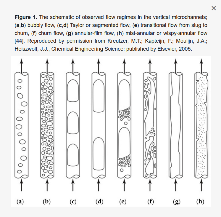
Slug regime
In the slug regime, interfacial tension is greater than inertial forces, and the Weber numbers are
Map of regime as a function of the two flows :
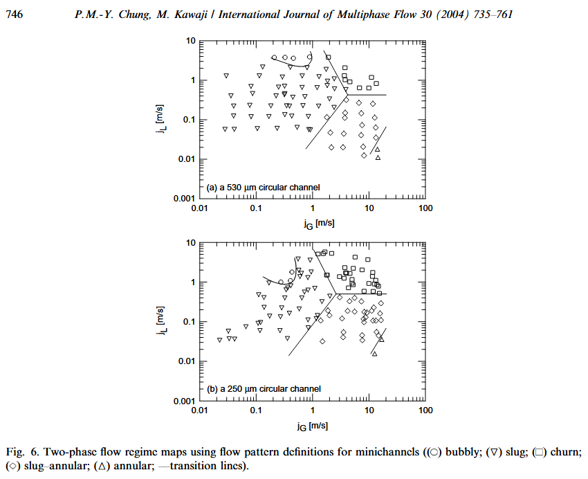
_Source : Chung, P.M.-Y., Kawaji, M., 2004. The effect of channel diameter on adiabatic two-phases flow characteristics in microchannels. International Journal of Multiphase Flow 30, 735–761
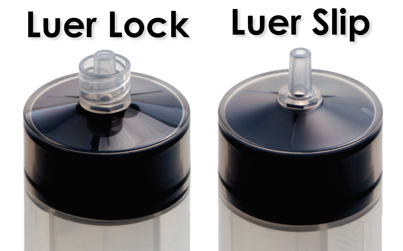
Attention pour des pressions importantes il faut utiliser un Luer Lock :
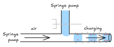
At Ca ≲ 0.01 and Reynolds number Re < 100 the interface sees mostly surface-tension forces. The T-junction pinches off the incoming air whenever the growing plug spans the channel, giving highly monodisperse “unit cells” of gas and liquid—a regime first mapped by Thorsen et al. and subsequently parameterised in many studies of T-junction droplet generators.
Longeur des train d'onde de gouttes
The scaling law that predicts the final droplet length,
where
where
where
SOURCE : Investigation of pressure profile evolution during confined micro-droplet formation using a two-phase level set method
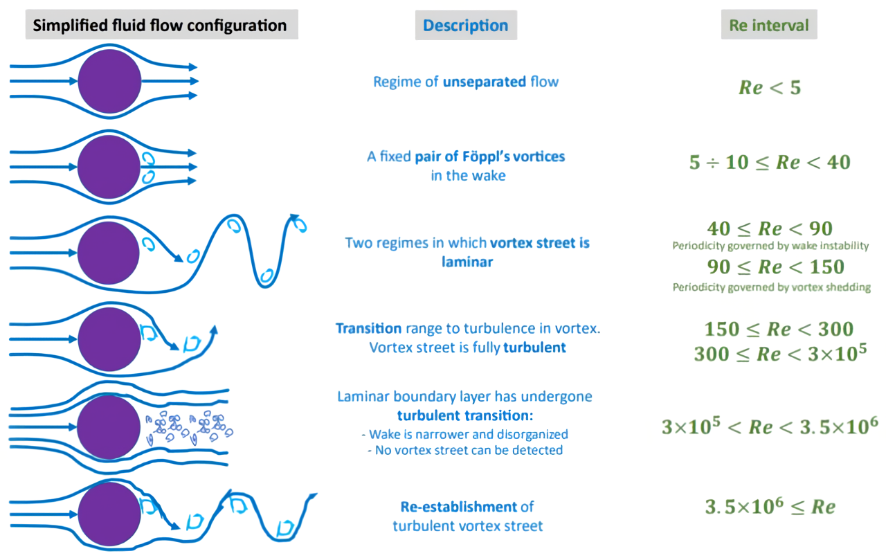
Further reading : Von Karman vortex streets